Products: Abaqus/Standard Abaqus/Explicit
This section provides basic verification tests for shell-to-solid coupling constraints.
S3R S4R S8R S9R5 STRI3 STRI65
C3D4 C3D8 C3D8R C3D10 C3D10HS C3D10M
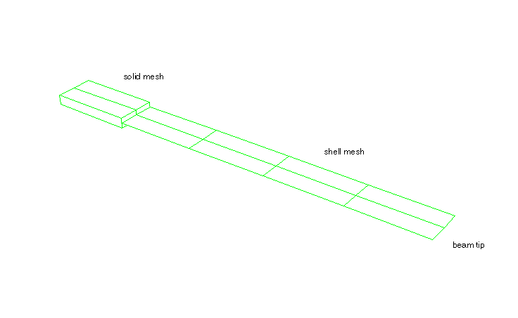
A cantilevered beam consisting of shell and continuum elements connected by shell-to-solid coupling constraints is subjected to various load conditions at the tip. The problem is analyzed with various combinations of shell and solid elements.
In addition, two input files are provided to illustrate how the shell-to-solid coupling constraints can be used to connect shell elements to continuum shell elements. In this case the continuum shell represents the solid interface.
Loading:
Step 1: A load of ![]() =60 is applied at the tip of the beam in a linear perturbation analysis.
=60 is applied at the tip of the beam in a linear perturbation analysis.
Step 2: A load of ![]() =60 is applied at the tip of the beam in a linear perturbation analysis.
=60 is applied at the tip of the beam in a linear perturbation analysis.
Step 3: A load of ![]() =–60 is applied at the tip of the beam in a large-displacement analysis.
=–60 is applied at the tip of the beam in a large-displacement analysis.
Step 4: A load of ![]() =60 is applied at the tip of the beam in a large-displacement analysis.
=60 is applied at the tip of the beam in a large-displacement analysis.
Step 5: The loads that were applied in the fourth step are removed.
Step 6: The boundary conditions are changed, and a rotation of ![]() around the z-axis is prescribed at tip of the beam.
around the z-axis is prescribed at tip of the beam.
For Abaqus/Explicit tests, the linear perturbation steps are omitted and the loading is as follows:
Step 1: A load of ![]() =–60 is applied at the tip of the beam in a large-displacement analysis.
=–60 is applied at the tip of the beam in a large-displacement analysis.
Step 2: A load of ![]() =60 is applied at the tip of the beam in a large-displacement analysis.
=60 is applied at the tip of the beam in a large-displacement analysis.
Step 3: The loads that were applied in the first two steps are removed.
Step 4: The boundary conditions are changed, and a rotation of ![]() around the z-axis is prescribed at the tip of the beam.
around the z-axis is prescribed at the tip of the beam.
The results for the general cases indicate that the shell edges and solid elements are coupled appropriately.
Shell-to-solid coupling tested between S3R shell elements and C3D4 continuum elements in a static analysis.
Shell-to-solid coupling tested between S3R shell elements and C3D8 continuum elements in a static analysis.
Shell-to-solid coupling tested between S3R shell elements and C3D10 continuum elements in a static analysis.
Shell-to-solid coupling tested between S3R shell elements and C3D10HS continuum elements in a static analysis.
Shell-to-solid coupling tested between S3R shell elements and C3D10M continuum elements in a static analysis.
Shell-to-solid coupling tested between S3R shell elements and C3D20R continuum elements in a static analysis.
Shell-to-solid coupling tested between S3R shell elements and C3D27R continuum elements in a static analysis.
Shell-to-solid coupling tested between S4R shell elements and C3D4 continuum elements in a static analysis.
Shell-to-solid coupling tested between S4R shell elements and C3D8 continuum elements in a static analysis.
Shell-to-solid coupling tested between S4R shell elements and C3D8 continuum elements in a static analysis with a node-based surface defined on the continuum elements.
Shell-to-solid coupling tested between S4R shell elements and C3D10 continuum elements in a static analysis.
Shell-to-solid coupling tested between S4R shell elements and C3D10HS continuum elements in a static analysis.
Shell-to-solid coupling tested between S4R shell elements and C3D10M continuum elements in a static analysis.
Shell-to-solid coupling tested between S4R shell elements and C3D20R continuum elements in a static analysis.
Shell-to-solid coupling tested between S4R shell elements and C3D20R continuum elements in a static analysis with a node-based surface defined on the continuum elements.
Shell-to-solid coupling tested between S4R shell elements and C3D27R continuum elements in a static analysis.
Shell-to-solid coupling tested between S4R shell elements and SC8R continuum shell elements in a static analysis.
Shell-to-solid coupling tested between S8R shell elements and C3D4 continuum elements in a static analysis.
Shell-to-solid coupling tested between S8R shell elements and C3D8 continuum elements in a static analysis.
Shell-to-solid coupling tested between S8R shell elements and C3D8 continuum elements in a static analysis with a node-based surface defined on the continuum elements.
Shell-to-solid coupling tested between S8R shell elements and C3D8 continuum elements in a static analysis with the OFFSET parameter used on the *SHELL SECTION option.
Shell-to-solid coupling tested between S8R shell elements and C3D10 continuum elements in a static analysis.
Shell-to-solid coupling tested between S8R shell elements and C3D10HS continuum elements in a static analysis.
Shell-to-solid coupling tested between S8R shell elements and C3D10M continuum elements in a static analysis.
Shell-to-solid coupling tested between S8R shell elements and C3D20R continuum elements in a static analysis.
Shell-to-solid coupling tested between S8R shell elements and C3D20R continuum elements in a static analysis with a node-based surface defined on the continuum elements.
Shell-to-solid coupling tested between S8R shell elements and C3D27R continuum elements in a static analysis.
Shell-to-solid coupling tested between S9R5 shell elements and C3D8 continuum elements in a static analysis.
Shell-to-solid coupling tested between STRI3 shell elements and C3D8 continuum elements in a static analysis.
Shell-to-solid coupling tested between STRI65 shell elements and C3D20R continuum elements in a static analysis.
Shell-to-solid coupling tested between S3R shell elements and C3D4 continuum elements in a static analysis.
Shell-to-solid coupling tested between S3R shell elements and C3D8R continuum elements in a static analysis.
Shell-to-solid coupling tested between S3R shell elements and C3D10M continuum elements in a static analysis.
Shell-to-solid coupling tested between S4R shell elements and C3D4 continuum elements in a static analysis.
Shell-to-solid coupling tested between S4R shell elements and C3D8R continuum elements in a static analysis.
Shell-to-solid coupling tested between S4R shell elements and C3D10M continuum elements in a static analysis.
Shell-to-solid coupling tested between S4R shell elements and SC8R continuum shell elements in a static analysis.
A cantilevered beam consisting of shell and continuum elements connected by shell-to-solid coupling constraints is subjected to various load conditions at the tip. The problem is analyzed with various combinations of shell and solid elements.
Loading:
Step 1: A frequency analysis is performed on the beam.
Step 2: The beam is bent in a large-displacement analysis.
Step 3: The beam is released, and a nonlinear dynamic springback analysis is performed.
For Abaqus/Explicit tests, the frequency analysis is omitted and the loading is as follows:
Step 1: The beam is bent in a large-displacement analysis.
Step 2: The beam is released, and a nonlinear dynamic springback analysis is performed.
The results for the general cases indicate that the shell edges and solid elements are coupled appropriately.
Shell-to-solid coupling tested between S4R shell elements and C3D4 continuum elements in a dynamic analysis.
Shell-to-solid coupling tested between S4R shell elements and C3D8 continuum elements in a dynamic analysis.
Shell-to-solid coupling tested between S4R shell elements and C3D10 continuum elements in a dynamic analysis.
Shell-to-solid coupling tested between S4R shell elements and C3D10HS continuum elements in a dynamic analysis.
Shell-to-solid coupling tested between S4R shell elements and C3D10M continuum elements in a dynamic analysis.
Shell-to-solid coupling tested between S4R shell elements and C3D20 continuum elements in a dynamic analysis.
Shell-to-solid coupling tested between S4R shell elements and C3D27 continuum elements in a dynamic analysis.
Shell-to-solid coupling tested between S8R shell elements and C3D4 continuum elements in a dynamic analysis.
Shell-to-solid coupling tested between S8R shell elements and C3D8 continuum elements in a dynamic analysis.
Shell-to-solid coupling tested between S8R shell elements and C3D10 continuum elements in a dynamic analysis.
Shell-to-solid coupling tested between S8R shell elements and C3D10HS continuum elements in a dynamic analysis.
Shell-to-solid coupling tested between s8r shell elements and C3D10M continuum elements in a dynamic analysis.
Shell-to-solid coupling tested between S8R shell elements and C3D20 continuum elements in a dynamic static analysis.
Shell-to-solid coupling tested between S8R shell elements and C3D27 continuum elements in a dynamic analysis.
Shell-to-solid coupling tested between S4R shell elements and C3D4 continuum elements in a dynamic analysis.
Shell-to-solid coupling tested between S3R shell elements and C3D8R continuum elements in a dynamic analysis.
Shell-to-solid coupling tested between S4R shell elements and C3D10M continuum elements in a dynamic analysis.
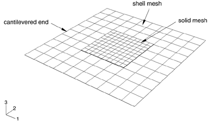
A free vibration analysis is carried out for a cantilevered thin square plate (see Figure 5.1.22–1). The outside section of the plate is modeled with shell elements, and the middle section of the plate is modeled with continuum elements coupled to the shell elements using shell-to-solid coupling constraints. The first six modes are extracted. The problem is analyzed with various combinations of shell and solid elements. These tests verify the ability of coupling constraints to model the shell-to-solid coupling accurately with an interface that includes corners. The free surface generation capability for both the shell and solid elements is also tested.
The natural frequencies and mode shapes compare well to the reference NAFEMS solution. The NAFEMS solution is taken from the National Agency for Finite Element Methods and Standards (U.K.): Test FV16 from NAFEMS publication TNSB, Rev. 3, “The Standard NAFEMS Benchmarks,” October 1990.
Test1 — S8R shell elements and C3D10 continuum elements (with and without free surface generation).
Test2 — S8R shell elements and C3D10HS continuum elements (with and without free surface generation).
Test3 — S8R shell elements and C3D20 continuum elements (with and without free surface generation).
Test4 — STRI65 shell elements and C3D10 continuum elements.
Test5 — STRI65 shell elements and C3D10HS continuum elements.
Test6 — STRI65 shell elements and C3D20 continuum elements.
Free vibration analysis of a cantilevered thin square plate with S8R shell elements and C3D10 continuum elements coupled together using shell-to-solid coupling constraints.
Free vibration analysis of a cantilevered thin square plate with S8R shell elements and C3D10 continuum elements coupled together using shell-to-solid coupling constraints. Free surface generation is used for both solid and shell surfaces.
Free vibration analysis of a cantilevered thin square plate with STRI65 shell elements and C3D10 continuum elements coupled together using shell-to-solid coupling constraints.
Free vibration analysis of a cantilevered thin square plate with S8R shell elements and C3D10HS continuum elements coupled together using shell-to-solid coupling constraints.
Free vibration analysis of a cantilevered thin square plate with S8R shell elements and C3D10HS continuum elements coupled together using shell-to-solid coupling constraints. Free surface generation is used for both solid and shell surfaces.
Free vibration analysis of a cantilevered thin square plate with STRI65 shell elements and C3D10HS continuum elements coupled together using shell-to-solid coupling constraints.
Free vibration analysis of a cantilevered thin square plate with S8R shell elements and C3D20 continuum elements coupled together using shell-to-solid coupling constraints.
Free vibration analysis of a cantilevered thin square plate with S8R shell elements and C3D20 continuum elements coupled together using shell-to-solid coupling constraints. Free surface generation is used for both solid and shell surfaces.
Free vibration analysis of a cantilevered thin square plate with STRI65 shell elements and C3D20 continuum elements coupled together using shell-to-solid coupling constraints.
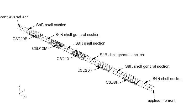
The pure bending of a cantilevered beam is modeled with an alternating mesh of shell and continuum elements. Ten separate shell-to-solid interfaces are modeled in this example. The beam is 22 in long, 1 in wide, and 0.25 in thick. The material is linear elastic with a Young's modulus of 30 × 106 psi and Poisson's ratio of 0.3. The reference tip displacement solution from classical linear elasticity for a moment of 400 lb-in is 2.4 in.
Loading:
Step 1: A moment of ![]() = 400 lb-in is applied at the tip of the beam in a linear perturbation analysis.
= 400 lb-in is applied at the tip of the beam in a linear perturbation analysis.
Step 2: A moment of ![]() = 400 lb-in is applied at the tip of the beam using NLGEOM for large-displacement analysis.
= 400 lb-in is applied at the tip of the beam using NLGEOM for large-displacement analysis.
The results for the general cases indicate that the shell edges and solid elements are coupled appropriately. The computed tip displacements for the linear perturbation and nonlinear analyses are 2.49 in and 2.48 in, respectively.
Shell-to-solid coupling tested for built-up beam in a static analysis.
The bending of a cantilevered beam is modeled with an alternating mesh of shell and continuum elements. Ten separate shell-to-solid interfaces are modeled in this example. The beam is 22 in long, 1 in wide, and 0.25 in thick. The material is linear elastic with a Young's modulus of 30 × 106 psi and ![]() The beam is subjected to a tip displacement of 2.4 in.
The beam is subjected to a tip displacement of 2.4 in.
Loading:
Step 1: A displacement of ![]() = 2.4 in is applied at the tip of the beam.
= 2.4 in is applied at the tip of the beam.
The results for the general cases indicate that the shell edges and solid elements are coupled appropriately.
Shell-to-solid coupling tested for built-up beam in a explicit dynamic analysis.