Product: Abaqus/Standard
Rotation of a substructure and the recovery of nodal and element variables, material directions, and integration point coordinates. The equation constraints, multi-point constraints, and nodal transformation are verified.
A rectangular substructure of length 10.0 and thickness and width 1.0 is formed and subjected to a pressure load of 200.0 on one end. The substructure is rotated 30° and fixed at the end opposite to the pressure load. A 2 × 5 mesh is used for solid and shell elements, and a 10-element mesh is used for beam elements.
A second mesh is defined in the rotated position and is loaded in the same manner as the first mesh, but without using substructures. The displacements, strains, and stresses, as well as the integration point coordinates and the material directions, should be identical for the elements within the substructure and the elements defined without using a substructure. The substructure stresses and strains are reported in the global system for continuum elements. In all other cases the substructure stresses and strains are reported in the rotated system.
The use of equation constraints, multi-purpose constraints, and nodal transformation is tested on the substructure comprised of CPE4 elements. The nodal transformation is tested both in the usage and in the creation level. Three levels of substructures are created for this particular analysis. The lowest level is a 2 × 1 mesh of CPE4 elements. The next level comprises two of the first-level substructures, and the third level is the actual structure. The use of unsorted retained degrees of freedom is tested during the creation levels.
All results in the substructure are identical to the results in the regular mesh and are within 0.05% of the analytical uniaxial solution.
CPE4 elements without *ORIENTATION.
Substructure generation file referenced in psupsol1.inp.
CPE4 elements with *ORIENTATION.
Substructure generation file referenced in psupsol1or.inp.
CPE4 elements with *TRANSFORM, *MPC, *EQUATION, and unsorted retained DOFs.
Substructure generation file referenced in psupsol1mi.inp.
Substructure generation file referenced in psupsol1mi.inp.
Substructure generation file referenced in psupsol1mi.inp.
SC8R elements with *SHELL SECTION and without *ORIENTATION.
Substructure generation file referenced in psupcontshl.inp.
S4R elements with *SHELL SECTION and without *ORIENTATION.
Substructure generation file referenced in psupshl1.inp.
S4R elements with *SHELL SECTION and *ORIENTATION.
Substructure generation file referenced in psupshl1or.inp.
S4 elements with *SHELL SECTION and without *ORIENTATION.
Substructure generation file referenced in psupsfl1.inp.
S4 elements with *SHELL SECTION and *ORIENTATION.
Substructure generation file referenced in psupsfl1or.inp.
S4R elements with *SHELL GENERAL SECTION and without *ORIENTATION.
Substructure generation file referenced in psupshl2.inp.
S4R elements with *SHELL GENERAL SECTION and *ORIENTATION.
Substructure generation file referenced in psupshl2or.inp.
S4 elements with *SHELL GENERAL SECTION and without *ORIENTATION.
Substructure generation file referenced in psupsfl2.inp.
S4 elements with *SHELL GENERAL SECTION and *ORIENTATION.
Substructure generation file referenced in psupsfl2or.inp.
B31 elements with *BEAM SECTION.
Substructure generation file referenced in psupbm1.inp.
B31 elements with *BEAM GENERAL SECTION.
Substructure generation file referenced in psupbm2.inp.
Translation, rotation, and mirroring of multilevel substructures and the recovery of nodal and element variables. These features are tested on two different models, a hemispherical shell and a simple hoist model. The hemispherical shell model is the same as that described in “LE3: Hemispherical shell with point loads,” Section 4.2.3 of the Abaqus Benchmarks Guide.
Two models are discussed below.
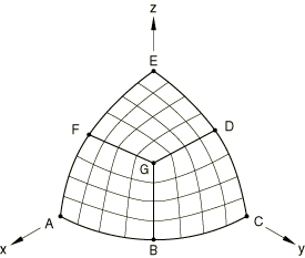
The mesh for the hemispherical shell problem in “LE3: Hemispherical shell with point loads,” Section 4.2.3 of the Abaqus Benchmarks Guide, consists of S4R5 elements. In that example one-eighth of the sphere is modeled. In this example the mesh is divided into three equal parts, as shown in Figure 3.4.1–1, with each part modeled with a 4 × 4 mesh of shell elements.
One of the three parts is defined (A - B - G - F), and a substructure is created. One-eighth of the sphere is then obtained by mirroring the substructure over lines F - G and G - B, respectively. The results from “LE3: Hemispherical shell with point loads,” Section 4.2.3 of the Abaqus Benchmarks Guide, are reproduced.
In the second example one-quarter of the sphere is modeled by using this substructure twice, the second time rotating it 90° around the z-axis.
In the third example one-half of the sphere is modeled by using the new substructure twice, the second time mirroring it in the x–z plane.
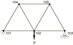
The overhead hoist shown in Figure 3.4.1–2 is used to test translation, rotation, and mirroring of a multilevel substructure. The hoist is a simple pin-jointed beam and truss model that is constrained at the left-hand end and mounted on rollers at the right-hand end. The members can rotate freely at the joints. Each member is 1 m in length and 5 mm in diameter. The structure is subjected to a 10 kN load at the center. The Young's modulus and Poisson's ratio of the members are taken to be 200 GPa and 0.3, respectively. The structure is modeled using seven T2D2 elements, one element for every member.
The horizontal member connected to the fixed end is used to form the first-level substructure. The second-level substructure representing the triangular section of the hoist is then formed by rotating and translating the first-level substructure. The third-level substructure representing the actual structure is created by mirroring or translating the lower-level substructures.
An independent model of the structure using regular T2D2 elements is also created to verify the results obtained.
The results for each model are discussed below.
All element output is in the local directions defined during the substructure formation.
| Mesh | Element | Sec. pt. | |||
|---|---|---|---|---|---|
| psuplev1 | 3000 < 1 | 1 | 377. | 2148. | 2581. |
| psuplev1 | 3000 < 2 | 1 | 377. | 2148. | 2581. |
| psuplev1 | 3000 < 3 | 1 | 1. | 1. | 700. |
| psuplev2 | 3000 < 1 < 101 | 1 | 377. | 2148. | 2581. |
| psuplev2 | 3000 < 2 < 101 | 1 | 378. | 2149. | 2580. |
| psuplev2 | 3000 < 3 < 101 | 1 | 2. | 1. | 699. |
| psuplev2 | 3000 < 1 < 102 | 1 | 377. | 2147. | 2581. |
| psuplev2 | 3000 < 2 < 102 | 1 | 378. | 2149. | 2580. |
| psuplev2 | 3000 < 3 < 102 | 1 | 2. | 1. | 700. |
| psuplev3 | 3000 < 1 < 101 < 1001 | 1 | 377. | 2148. | 2581. |
| psuplev3 | 3000 < 3 < 101 < 1001 | 1 | 2. | 1. | 699. |
| psuplev3 | 3000 < 1 < 102 < 1001 | 1 | 377. | 2147. | 2581. |
| psuplev3 | 3000 < 1 < 101 < 1002 | 1 | 377. | 2148. | 2581. |
| psuplev3 | 3000 < 2 < 101 < 1002 | 1 | 378. | 2149. | 2580. |
| psuplev3 | 3000 < 1 < 102 < 1002 | 1 | 377. | 2147. | 2581. |
| psuplev3 | 3000 < 2 < 102 < 1002 | 1 | 378. | 2149. | 2580. |
| psuplev3 | 3000 < 3 < 102 < 1002 | 1 | 2. | 1. | 700. |
This is an analysis of one-eighth of a sphere.
Forms the first-level substructures; referenced in analysis psuplev1.inp.
This performs the analysis of one-fourth of a sphere by using two of the substructures, the second one rotated 90°.
Forms the second-level substructures by using three of the first-level substructures: one in the original geometric location and two by mirroring the element; referenced in analysis psuplev2.inp.
This performs the global analysis by using two copies of the substructure: one in the original position and one by mirroring.
Forms the third-level substructures by using two of the second-level substructures: one in the original geometric location and the other by rotating the substructure 90°; referenced in analysis psuplev3.inp.
Analysis of a simple overhead hoist model using substructures.
Substructure generation file referenced in psuphoi1.inp.
Substructure generation file referenced in psuphoi1.inp.
Analysis of overhead hoist model without substructures.
Substructure rotation that activates degrees of freedom that were not retained during substructure generation.
A substructure is defined along the global x-axis by retaining the x-displacement degree of freedom at both nodes of a T2D2 element. The substructure property definition is used to rotate the substructure 45° in the x–y plane. One end of the substructure is fixed, whereas displacement boundary conditions corresponding to axial tension are applied at the free end.
The results from the substructure analysis exactly match the results that were obtained when substructures were not used. The degrees of freedom that were not retained during substructure generation are activated properly by the use of the substructure property definition.
Uses one T2D2 element.
Substructure generation file referenced in psuptr1.inp.
Inclusion of deformable elements that are declared as rigid during substructure generation and subsequent usage is verified.
The use of deformable elements that are declared as rigid is tested at the substructure generation level and at the usage level. The substructure mesh consists of 10 beam elements with one of the elements declared as rigid. A pressure load of 200.0 is applied on one end. The substructure is rotated 30° and fixed at the end opposite to the pressure load. A second mesh is defined in the rotated position and loaded in the same manner as the substructure mesh. This mesh consists of beam elements with one of the elements declared as rigid. Substructures are not included in this mesh. The displacements, strains, and stresses should be identical for the elements within the substructure and the elements defined without using a substructure.
All results in the substructure are identical to the results in the regular mesh.
A deformable element is declared as rigid at the substructure generation level and at the usage level.
Substructure generation file referenced in psupbm11.inp.