If you use wire parts to model beams, you must create a beam section that refers to a beam profile, and you must assign the beam section to the wire part. In addition, you must assign a beam orientation to the wire part. You can then use the View![]() Part Display Options and the View
Part Display Options and the View![]() Assembly Display Options menu items to view a realistic display of the beam profile in parts and the assembly in the current viewport.
Assembly Display Options menu items to view a realistic display of the beam profile in parts and the assembly in the current viewport.
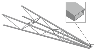
When beam profiles are displayed, Abaqus/CAE disables both view cuts and scaling and shrinking of the model. Displaying beam profiles is useful for checking that the correct profile has been assigned to a particular region and that the assigned beam orientation results in the expected orientation of the profile. For example, Figure 76–6 shows the box beam profiles displayed on the light-service crane described in “Example: cargo crane,” Section 6.4 of Getting Started with Abaqus/CAE.
If you assign a general beam section to a wire, Abaqus/CAE displays the beam profile as an ellipse with a cross-sectional area and moments of inertia (![]() and
and ![]() ) that match the values you specified. If you assign a truss section to a wire, Abaqus/CAE displays the truss profile as a circle with a cross-sectional area that matches the value you specified.
) that match the values you specified. If you assign a truss section to a wire, Abaqus/CAE displays the truss profile as a circle with a cross-sectional area that matches the value you specified.
Abaqus/CAE does not render the tapering of beam profiles along their length. If your model includes tapered beam sections, Abaqus/CAE renders these beams using the beam's starting profile along its entire length. For more information about tapered beams, see “Creating beam sections,” Section 12.13.11.
Abaqus/CAE renders beam profiles according to the current settings for color coding and translucency. When these settings change, the color and translucency of the beam profiles change as well.
To control beam profile display:
Locate the Render beam profiles option.
From the main menu bar, select View![]() Part Display Options or View
Part Display Options or View![]() Assembly Display Options. In the dialog box that appears, click the General tab.
Assembly Display Options. In the dialog box that appears, click the General tab.
From the bottom of the dialog box, toggle on Render beam profiles to display beam profiles.
If desired, apply a Scale factor to the beam profiles to increase or decrease their size. The default value is 1.
Click OK to implement your changes and to close the dialog box.
Abaqus/CAE displays the profile of the beam section with the appropriate dimensions and in the correct orientation. Your changes are saved for the duration of the session.