
You can partition selected faces by sketching the geometry of the partition using the Sketcher. You use the Sketcher when you want to create a partition whose shape cannot be achieved with any of the other partition tools. Sketching a partition offers other advantages:
You can use the Feature Manipulation toolset to modify the sketch if you want to change the shape or the position of the partition.
You can dimension the sketch precisely, and you can use the Feature Manipulation toolset to modify the dimensions.
If the faces to be partitioned are planar and lie in the same plane, you can sketch directly on that plane. Your sketch can extend beyond the boundaries of the selected faces, but the partition will not extend beyond the edge of the faces. The following figure illustrates a sketched partition on a planar face:

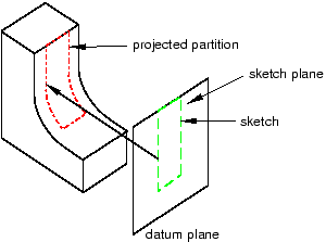
If any of the faces to be partitioned are nonplanar or do not lie in the same plane, you must select a planar face or datum plane on which to sketch. Abaqus/CAE creates the partition by projecting the sketch onto the faces to be partitioned. You can specify the direction of the projection and the distance of the projection, normal to the sketch plane. The following figure illustrates a sketched partition on a nonplanar face using the projection of a sketch drawn on a datum plane:
To partition faces using the sketch method:
From the main menu bar, select Tools![]() Partition.
Partition.
The Create Partition dialog box appears. Abaqus/CAE displays prompts in the prompt area to guide you through the procedure.
Tip:
You can also use the sketch method to partition faces using the ![]() tool, located with the partition face tools in the module toolbox. For a diagram of the partition tools in the toolbox, see “Using the Partition toolset,” Section 70.2.
tool, located with the partition face tools in the module toolbox. For a diagram of the partition tools in the toolbox, see “Using the Partition toolset,” Section 70.2.
From the Type radio buttons at the top of the dialog box, choose Face.
The Method list displays the methods that you can use to partition a face.
From the list of methods, select Sketch.
If the part or assembly contains only one face, Abaqus/CAE enters the Sketcher.
If the part or assembly contains more than one face, select the faces to partition and click mouse button 2. You can use a combination of drag select, [Shift] + Click, [Ctrl] + Click, and the angle method to select more than one face to partition. For more information, see “Selecting objects within the current viewport,” Section 6.2.
Tip: If you are unable to select the desired faces, you can use the Selection toolbar to change the selection behavior. For more information, see “Using the selection options,” Section 6.3.
If the part or assembly is two-dimensional or axisymmetric, Abaqus/CAE enters the Sketcher and highlights the selected faces.
If the part or assembly is three-dimensional and the selected faces are planar, select an edge and the orientation of the edge on the Sketcher grid. The edge must not be perpendicular to the sketch plane. By default, the selected edge will appear vertical and on the right side of the Sketcher grid. To choose a different orientation for the edge, click the arrow on the right side of the dialog box and choose an orientation from the list that appears.
Tip: If the part or assembly does not have an edge that will provide the desired orientation, you can create a datum axis. You can then select the datum axis to control the orientation of the part on the Sketcher grid.
Abaqus/CAE highlights the selected edge, enters the Sketcher, and rotates the part until the selected planar face or datum plane aligns with the plane of the Sketcher grid and the selected edge aligns with the grid in the desired orientation. Abaqus/CAE highlights the selected faces.
If the part or assembly is three-dimensional and the selected faces are nonplanar or do not lie in the same plane, do the following:
Select a planar face or a datum plane on which to sketch. Abaqus/CAE highlights the selected face.
From the buttons in the prompt area, select a method to determine how far Abaqus/CAE projects the sketch normal to the sketch plane. The partition is created wherever the projected sketch extends through the selected faces. The three methods are illustrated in the following figure:

If you selected the Through All method, Abaqus/CAE asks you to choose which direction the sketch will be projected.
If you selected the Enter Value method, Abaqus/CAE asks you to choose the distance and direction that will be used to project the sketch. The default distance that Abaqus/CAE provides generates a partition that extends completely through the selected faces (resulting in the same partition as selecting Through All). The Feature Manipulation toolset allows you to modify the projection distance after you create the partition.
If you selected the Select Point method, Abaqus/CAE asks you to choose the point to which the sketch will be projected; the point defines both the direction and the projection distance.
Select an edge and the orientation of the edge on the Sketcher grid. The edge must not be perpendicular to the sketch plane. By default, the selected edge will appear vertical and on the right side of the Sketcher grid. To choose a different orientation for the edge, click the arrow on the right side of the dialog box and choose an orientation from the list that appears.
Tip: If the part or assembly does not have an edge that will provide the desired orientation, you can create a datum axis. You can then select the datum axis to control the orientation of the part on the Sketcher grid.
Abaqus/CAE highlights the selected edge, enters the Sketcher, and rotates the part until the selected planar face or datum plane aligns with the plane of the Sketcher grid with the projection direction into the screen and the selected edge aligns with the grid in the desired orientation. Abaqus/CAE highlights the selected faces.
Use the Sketcher to sketch the partition. From the main menu bar, click Done to indicate you have finished sketching the partition.
In the prompt area, click Create Partition.
Abaqus/CAE creates the partition.
