This example shows how you can use the midsurface modeling tools in Abaqus/CAE to convert a solid model of a bracket to a shell representation of the same part.
The solid model
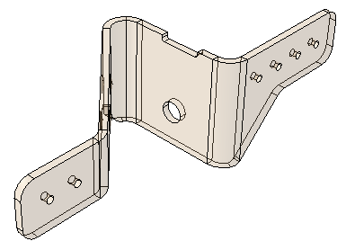
The model in this example is a 175.0 mm long bracket that is stamped from a 3.0 mm thick plate of mild steel, as shown in Figure 35–3. A default mesh of the solid part results in one or two elements through the thickness of the bracket that will not perform well in bending. Modeling a shell representation of the bracket will provide a more accurate bending response.
Assign the midsurface region
Use the Assign Midsurface Region tool in the Part module to remove geometry from the active representation of the model and to create a reference representation of the original solid geometry, as shown in Figure 35–4.
The reference representation is an abstract representation of the original bracket. It retains the original geometry of the bracket, but it cannot be used in the analysis. The reference representation appears by default in the Part module; you can toggle the view off and on using the Show Reference Representation toolCreate the shell representation
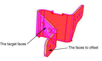
You must create a shell representation of the bracket that can be analyzed by Abaqus. The most commonly used tool for creating a midsurface shell model is the offset face tool, located with the other face tools in the Geometry Edit toolset. The offset face tool allows you to select one or more faces from the reference representation and to create new faces that are offset from the original faces. You can enter a fixed distance, or you can select target faces that Abaqus/CAE uses to calculate the distance. If you select target faces, the resulting shell thickness varies if the distance between the face to offset and the target face is not constant. Abaqus/CAE calculates the nodal thickness and the element offset for each node and element when you analyze the model. The Offset Faces dialog box is shown in Figure 35–5.
For more information, see “An overview of the methods for editing faces,” Section 69.2.2, and “Adding a shell feature,” Section 11.22.Figure 35–6 shows the selected faces to offset and the selected target faces. The by angle selection method was used to select the inner group of face as the faces to offset and the outer group of faces as the target faces.
In this example you select the default option of Half the average distance from the Offset Faces dialog box, and Abaqus/CAE creates faces that are half the average distance between the faces to offset and the target faces.
By default, Auto trim to reference representation is toggled off in the Offset Faces dialog box. However, the auto trim option was active for this step, so Abaqus/CAE trimmed the offset faces to align with the reference representation. In some cases the trimming operation fails, which results in a slight misalignment between the new faces and the reference representation and a warning message from Abaqus/CAE. Even when trimming fails, the resulting shell face is often still a reasonable approximation of the reference representation; so you may be able to ignore the warning message. For more information, see “Using the offset face tool for midsurface modeling,” Section 35.3.1.
Assign a shell section
You use the Property module to create a shell section and to assign it to the new face. When you create the shell section, you can enter an arbitrary value for the shell thickness. When you subsequently assign the section to the shell, you specify that the thickness and the shell offset are calculated from the geometry in the Edit Section Assignment dialog box, as shown in Figure 35–7. Abaqus/CAE ignores the thickness value that you entered for the shell section.
For more information, see “Assigning a section,” Section 12.15.1.If desired, you can toggle on Render shell thickness from the Part Display Options to view the thickness of the shell, as shown in Figure 35–8.
Mesh the part
Abaqus/CAE colors the shell part pink in the Mesh module to indicate it can be meshed using the free meshing technique, as shown in Figure 35–9.
You apply automatic virtual topology to the part to remove small details from the original part and to remove details that were created during the face trimming operation, as described in “Creating virtual topology automatically,” Section 75.6.1.You apply default seeding and mesh controls, and the resulting mesh is shown in Figure 35–10.