Gaskets are thin sealing components that are positioned between structural components. (For detailed information on gasket theory, see “Gasket elements,” Section 32.6 of the Abaqus Analysis User's Guide.) The general procedure for modeling gaskets in three-dimensional space involves the following steps:
In the Part module, define the solid geometry. Gasket parts are typically very thin, flat solids.
In the Property module, define a gasket material. The material can be a regular material or one that includes special gasket behaviors. See “Defining materials for gaskets,” Section 32.2, for more information.
In the Property module, define a gasket section that refers to the gasket material. Then assign the gasket section to the gasket region.
In the Interaction module, establish appropriate tie constraints or contact interactions between the gasket surfaces and the surfaces of adjacent regions.
In the Mesh module, assign the top-down swept meshing technique or the bottom-up meshing technique to the gasket region. Regardless of the meshing technique that you choose, you must sweep, extrude, or revolve the mesh in a direction normal to the gasket plane to produce gasket elements with the correct orientation. See “Specifying the sweep path,” Section 17.18.6, or “Bottom-up meshing,” Section 17.11, for more information.
In the Mesh module, assign a gasket element type to the gasket region, and mesh the region.
When you model gaskets with solids, you can use one or a combination of the following techniques to define the interaction between the gaskets and surrounding regions:
You can create a separate gasket part and then use tie constraints or contact interactions to couple the gasket part instance to the other part instances.
You can create a thin region within a part and then assign a gasket section and element type to that region. This approach is recommended if compatibility between the gasket mesh and the meshes of adjacent regions is important.
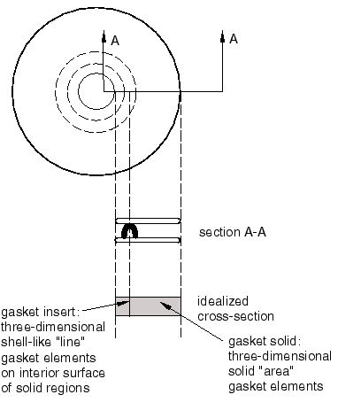
Additional steps are necessary if the gasket model is composed of several layers and inserts. For example, Figure 32–1 illustrates a gasket modeled as a solid layer with an embedded shell-like insert.
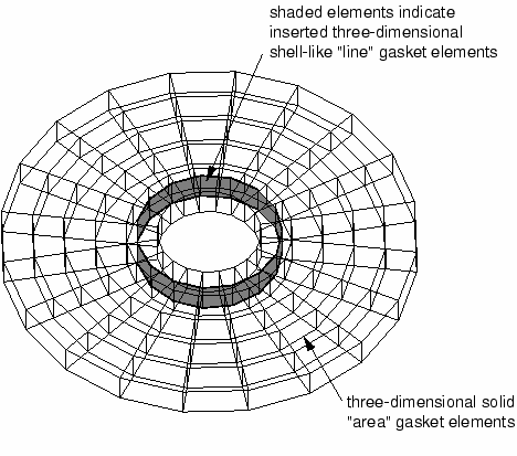
The Abaqus/CAE representation of the idealized gasket model is shown in Figure 32–2.
If you are working with gaskets composed of several layers and inserts, you must perform the following additional tasks:Use the Partition toolset to partition the solid gasket region so that an internal surface is created at the position of the insert.
In the Property module, define a skin reinforcement on the internal surface that represents the insert. (See “Defining skin reinforcements,” Section 36.1, for more information.) The gasket sections that you assign to the solid and to the insert are usually different, as are their materials.
No meshing is required (or allowed) for the insert skin, but you must assign a three-dimensional “line” gasket element type to the skin in the Mesh module. See “Assigning element types to skin or stringer reinforcements,” Section 36.5, for more information.