Assembled fasteners let you efficiently assign complex fastener behaviors in a large number of model locations. Using the assembled fastener technique, you can read in connector and constraint behaviors from a template model and assign these attributes in multiple locations in your main model. For a large system such as an airframe or automobile, assembled fasteners allow you to define the fastener template once and then assign it many times in the main model. With the appropriate use of coupling constraints and adjust points constraints, slave nodes in the template model can be automatically resized in the main model to accommodate the actual surface spacing.
The overall process for building assembled fasteners is as follows:
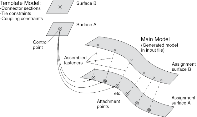
Build the template model containing your fastener-like construct: connector section assignments, tie constraints, coupling constraints, and solid or beam section assignments. You must assign names to all surfaces involved in constraints. You must also define a single-point set as the control point, which will be used to locate the template model copies in the main model.
Develop your main model, placing attachment points at the locations where you want the template fastener to be replicated. The template model control point will be mapped onto the locations of the attachment points in the main model (see Figure 29–5).
Working in your main model, use the Create Fasteners and Edit Fasteners dialog boxes to define how the template model will be read in, assigned, and oriented.
Optionally, use one or more property generation scripts to modify the properties copied into the main model from the template model. Multiple property generation scripts can be used with the same template model to achieve different results in separate assembled fastener objects. For example, you could use two scripts to apply different materials to the same fastener template. You can use the Abaqus Scripting Interface to write your property generation scripts; see “Creating and running your own scripts,” Section 9.5.4, and the Abaqus Scripting User's Guide.
The template model uses the global coordinate system, and the positive Z-axis direction of the fastener construct will be aligned with the selected normal direction in the main model.
Assembled fasteners are different from point-based (mesh-independent) and discrete fasteners in Abaqus/CAE. Assembled fasteners do not create individual fastener objects like point-based and discrete fasteners, but instead they allow you replicate fastener-like behavior in many places. You cannot view or manipulate the individual fasteners (at each attachment point) in the main model while working in the Abaqus/CAE GUI; they are produced only in the input file generated by Abaqus/CAE. The template model sets are aggregated in the input file generated by Abaqus/CAE to help you manage models containing large numbers of assembled fasteners.
Assembled fastener template models are intended only to model fastener-like constructs and do not provide a generic subassembly capability. Only a few Abaqus/CAE features are supported in template models, such as connectors and mass inertia. No other Abaqus/CAE features are allowed in template models.
Table 29–1 lists the features that are supported and read from the template model into the main model.
Table 29–1 Features supported in assembled fastener template models.
| Beam and solid parts (beam, solid, and cohesive elements) |
| Beam and solid section assignments (but not distributions or composite layups) |
| Connector section assignments |
| Tie constraints and coupling constraints (except for tie constraints generated due to incompatible meshes) |
| Adjust points constraints |
| Mass inertia |
Table 29–2 Features that are not supported in assembled fastener template models.
| Point-based (mesh-independent) and discrete fasteners |
| Attachment points |
| Analytical rigid surfaces |
| Orphan mesh surfaces |
| Tie constraints generated internally due to incompatible meshes |
| Any constraint type other than tie, coupling, or adjust points |
Solid parts are allowed in the template model but material orientations are not.
Beam parts are allowed in the template model, but beam orientations must be assigned using the same region as the beam section assignment.
Solid and beam parts are allowed, but complex parts/assemblies may not work.
Unmeshed constraint surfaces in the template model are allowed.
Shell parts are not allowed in the template model, except as reference surfaces for constraints. These constraint surfaces will effectively be replaced with main model surfaces when the input file is generated by Abaqus/CAE. All constraint surfaces should be substituted with main model surfaces for correct behavior of the assembled fastener.
Template model surfaces are not copied into the main model when the input file is generated by Abaqus/CAE. The only surfaces allowed in the template model are those that will have main model surfaces substituted for them.
Constraint surfaces cannot be orphan mesh surfaces.
Reference points are allowed in template models, but attachment points are not allowed.
The modeling space of the template models must match the modeling space of the main model (see “Part modeling space,” Section 11.4.1).
Coupling constraints in the template model must constrain all degrees of freedom and must not specify a local coordinate system.
Tie constraints in the template model must use a generic master surface and a slave node region, not a slave surface.
Point mass and rotary inertia features are allowed in template models. However, for rotary inertia the local coordinate system will be ignored; thus, the only useful scenario is ![]() =
= ![]() =
= ![]() , and
, and ![]() =
= ![]() =
= ![]() = 0. Essentially, the rotary inertia feature must have rotational symmetry.
= 0. Essentially, the rotary inertia feature must have rotational symmetry.
The control point must be a predefined set containing a single vertex or node in your template model. You must create this set in the template model before creating the assembled fasteners in your main model. When the template model is read in, the control point will be placed at the locations of your attachment points in the main model.
The constraint surfaces in the template model must be mapped to corresponding surfaces in the main model to enable the constraint behavior in the main model. When you define the assembled fasteners in the main model, the Edit Fastener dialog box will automatically prepopulate the surface assignment table with any template model surfaces involved in tie constraints, coupling constraints, or adjust points constraints. The template surfaces are initially listed in ascending Z-axis order using the template model global coordinate system. You can change the order to coincide with your template fastener design; however, the ordering of the surfaces is not significant beyond the selection of the first surface, because the corresponding assignment surface normal is used to orient the assembled fastener. In the main model you must assign names to the surfaces that will be involved in the assembled fastener constraints.
At each attachment point in the main model, the template model is positioned and translated so that the template model control point coincides with the attachment point. The template model is rotated into the main model and oriented such that the positive Z-axis of the global coordinate system of the template model aligns with the coordinate system you specify (on the Orientations tabbed page of the Edit Fasteners dialog box). The default is to orient the template model copies according to the normal vector of the first surface in the main model. This default orientation from the first surface normal creates a Z-axis alignment at every attachment point. The X-axis is then computed by projecting the global X-axis onto the surface.
For any sets that you create in the template model, the main model will aggregate all of the sets' objects into a single set per assembled fastener. When the input file is generated by Abaqus/CAE, template model sets will be aggregated across all attachment points of the assembled fastener. For example, consider a template model that contains a connector section assignment for a wire set named Wire-1-Set-1, and that set contains a single wire. If the assembled fastener is then placed at 10 attachment points in the main model, the main model will have a set named TM-1_Wire-1-Set-1 that contains 10 wires. However, Abaqus/CAE generates these aggregated sets only when it creates the input file. The aggregated sets are not directly visible in Abaqus/CAE.
Note: The Adjust control point to lie on surface option can be useful in coupling constraints you create in assembled fastener template models; see “Defining coupling constraints,” Section 15.15.4. The more general-purpose adjust points constraint can also be useful in assembled fastener template models; see “Defining adjust points constraints,” Section 15.15.5.
The adjust points capability should not be used in assembled fastener template models when the main model attachment points are located at bolt hole center points. Any point along the bolt hole centerline will be moved (incorrectly) to a random location along the perimeter of the hole instead of being projected along the surface normal to the center of the hole.
Note: The size and shape of the template model surfaces do not matter, except with regard to the display of those surfaces during template model rendering from the Edit Fasteners dialog box. The recommended best practice is to make your template model surfaces square or rectangular in shape to facilitate rendering speed and accuracy in the main model. Circular template model surfaces or surfaces with any curvature will be rendered in a crudely approximate fashion in the main model.
Each assembled fastener can optionally reference a script that will modify the template model properties; for example, to use different materials in the assembled fasteners. These property generation scripts can be used to calibrate or adjust the fastener properties. In Abaqus/CAE property definitions include material, profile, section, and connector section definitions.
You can use the Abaqus Scripting Interface to write your property generation scripts; see “Creating and running your own scripts,” Section 9.5.4, and the Abaqus Scripting User's Guide.
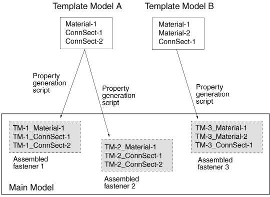
This feature lets you use the same template model multiple times with different property generation scripts. The property definitions from the template model are copied into the main model and given names based on the original names plus a prefix. The default prefix is TM-1 for the first assembled fastener you create, and TM-2, TM-3, etc., for subsequent ones. For example, a connector section named BoltSection in the template model will be named TM-1_BoltSection in the main model. You can change the prefix on the Properties tabbed page of the Edit Fasteners dialog box. Property prefix strings must be unique for all assembled fasteners you create.
Figure 29–6 shows an example in which two template models are used with three different property generation scripts.
A complete example of a property generation script is provided in the blog post “Property generation scripts for assembled fasteners in Abaqus/CAE” in the SIMULIA Learning Community. The script uses a method named getSurfaceSections that is useful for assembled fastener property scripts. This method accepts a surface name and returns a list of all section names found on the geometry underlying the named surface region; see “getSurfaceSections,” Section 6.1.12 of the Abaqus Scripting Reference Guide. The getSurfaceSections method can be used to obtain section information such as the material name and thickness, as shown in the code fragment below.
    def __init__(self, scriptName, modelName, fastenerName):
        self.scriptName   = scriptName
        self.modelName    = modelName
        self.fastenerName = fastenerName
        print 'Running script "%s" for "%s"' % (scriptName,
          fastenerName)
        assy = mdb.models[modelName].rootAssembly
        eo = assy.engineeringFeatures.fasteners[fastenerName]
        print eo.assignedSurfaces
        diameter = getInput('Enter %s bolt diameter:' % scriptName)
        print '  Bolt diameter: %s' % diameter
        for aSurf in eo.assignedSurfaces:
            sectNames = assy.getSurfaceSections(aSurf)
            print '  %s: %s' % (aSurf, sectNames)
            # No section assigned
            if (len(sectNames) > 0 and sectNames[0] == ''):
                continue
            for section in sectNames:
                sectObj = mdb.models[modelName].sections[section]
                if (type(sectObj) == HomogeneousShellSectionType):
                    print '    %s:  mat=%s, thk=%s' % \
                        (section, sectObj.material, sectObj.thickness)
You provide the file name of the property generation script on the Properties tabbed page of the Edit Fasteners dialog box. The script is executed only when you click OK in the Edit Fasteners dialog box, not when Abaqus/CAE creates the input file. The property generation script is run only in the main model on the assembled fasteners, not in the template model.
To make your property generation scripts available from the Edit Fasteners dialog box, you must register each script similar to the way in which you register an Abaqus/CAE plug-in. The script must be registered before you startAbaqus/CAE. Any scripts that have been registered will be available from a pull-down list in the Edit Fasteners dialog box.
To register a property generation script, you must write a small registration script containing the following lines:
from abaqusGui import *
toolset = getAFXApp().getAFXMainWindow().getPluginToolset()
toolset.registerAsmbdFastenerScript('filename')
This registration script file must be named registerAsmbFstnrScripts_plugin.py. In the code replace filename with the name of your property generation script. The registration script informs Abaqus/CAE that you have a property generation script named filename.py that you wish to use with assembled fasteners.Your property generation scripts and the registration script must be placed in your abaqus_plugins directory; see “Where are plug-in files stored?,” Section 81.6.1 , for the possible locations of the abaqus_plugins directory. For more details about registration scripts, see “What are the kernel and GUI registration commands?,” Section 81.6.2 .
You can obtain both field output and history output from assembled fasteners in your main model. The output must be requested on named sets that you have defined in the template model.
To request output for assembled fasteners:
In the Step module, working in your main model (not the template model), display the Edit History Output Request dialog box or the Edit Field Output Request dialog box; see the instructions in “Creating and modifying output requests,” Section 14.4.5.
From the Domain list, choose Assembled fastener set.
From the Fastener list, choose the name of the assembled fastener for which you want output.
From the Set list, choose any set from the template model. The assembled fastener in your main model references the sets defined in the template model.
Continue selecting output variables and other options, and click OK to save your request.

Assembled fasteners and point-based (mesh-independent) fasteners produce slightly different analysis results when used for the same fastener model. Assembled fasteners and point-based fasteners will generate different coupling nodes and coupling weights, leading to different solutions. The differences between point-based and assembled fasteners are described below and in Figure 29–7 and Figure 29–8.
Point-based fasteners
Abaqus looks at the first node of the connector and projects it onto the first surface (given the data line). Abaqus then moves normal to the facet, where it finds the first projection point and finds the subsequent projection points on the second surface.
Assembled fasteners
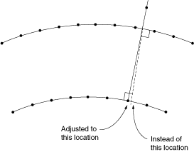
When the assembled fastener is instanced in the main model, Abaqus places the first node of the connector where the first projection point of the point-based fastener model is located. Both fastener types accomplish this placement with normal projections. However, for assembled fasteners an adjust point constraint is performed on the second node of the connector; i.e., a normal projection onto the second surface. This action is not the same as moving normal to the first projection point facet unless the two normals align perfectly. Therefore, the second (subsequent) attachment points can be different for assembled fasteners versus point-based fasteners, which will lead to differences in the analysis solution.
In an ideal case where the two surfaces are placed exactly the same distance apart as the template model connector and are parallel to each other, Abaqus will get the same projection points for assembled fasteners and point-based fasteners. However, this situation will not be the case in general.