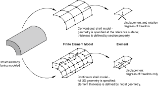
You use conventional shell parts to model structures in which the thickness is significantly smaller than the other dimensions, and you define the thickness in the Property module when you create the section. In contrast, you assign continuum shell elements to solid parts, and Abaqus determines the thickness from the geometry of the part. From a modeling point of view continuum shell elements look like three-dimensional continuum solids, but their kinematic and constitutive behavior is similar to conventional shell elements. For example, conventional shell elements have displacement and rotational degrees of freedom, while continuum solid elements and continuum shell elements have only displacement degrees of freedom. For more information, see “Shell elements: overview,” Section 29.6.1 of the Abaqus Analysis User's Guide, and “Choosing a shell element,” Section 29.6.2 of the Abaqus Analysis User's Guide. Figure 25–1 illustrates the differences between a conventional shell and a continuum shell element.
The general procedure for modeling continuum shells in three-dimensional space involves the following steps:
In the Part module, define the solid geometry.
In the Property module, assign a shell section to any solid regions to which you will assign continuum shell elements in the Mesh module. You must specify the thickness of a shell section; however, Abaqus uses this thickness only to estimate certain section properties, such as hourglass stiffness. Abaqus uses the actual thickness, based on the element nodal geometry, during the analysis. If the thickness of the solid region varies along its length, you should provide an approximate value of the thickness. For more information, see “Using a shell section integrated during the analysis to define the section behavior,” Section 29.6.5 of the Abaqus Analysis User's Guide.
In the Mesh module, query the mesh stack orientation. If necessary, assign a stack orientation so that the continuum elements are aligned consistently from the bottom to the top of the stack. See “Applying a mesh stack orientation,” Section 17.18.8, for more information.
In the Mesh module, assign a continuum shell element type to the region, and mesh the region with hexahedral or wedge elements. These are the only elements that can be stacked to form a continuum shell mesh.