You can use swept meshing to create a mesh on cylindrical geometry with many types of solid elements, including elements from the solid cylindrical element library. If you use solid cylindrical elements for a native mesh, Abaqus/CAE uses the sweep path of the selected sweep/revolve region as the circumferential direction for the generated cylindrical elements. You should confirm that the sweep path is set correctly before creating the mesh.
Abaqus considers the following requirements for cylindrical elements when you attempt to mesh solid geometry with cylindrical elements:
The midside nodes on the circular edges of the cylindrical elements must be placed exactly halfway between the edge nodes.
All nodes on a cross-section must lie on the same radial plane.
All the circular edges within an element must span the same angle.
The centers of the circular arcs within an element must lie on a common axis.
An element cannot span more than 180°.
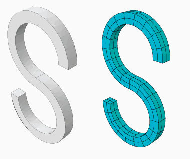
These requirements mean that you can create valid cylindrical elements only on revolved parts or parts that you can split into revolved domains. The S-shaped extrusion in Figure 17–81 can be meshed with cylindrical elements after partitioning into revolved regions.
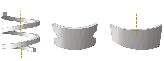
Figure 17–82 shows three types of geometry—a helical spring, a revolved part with cuts, and a tapered part—that cannot be meshed with solid cylindrical elements because of these meshing requirements.If one of the connecting sides that connect the source face to the target face in a revolved region is separated into multiple faces due to the internal edge or edges that constrain the mesh, the generated elements are likely to be too distorted to be used as cylindrical elements. You must partition the solid region into simpler revolved regions, as shown in the example on the right side of Figure 17–83.
Figure 17–83 A solid region that is unsuitable for meshing with cylindrical elements (left) and the same region rendered suitable for meshing with cylindrical elements through the use of a partition (right).

When you edit a mesh part by assigning cylindrical elements to it, Abaqus/CAE considers Face 1 and Face 2 of each cylindrical element to be the faces along its radial planes. Figure 17–84 indicates the location of these faces for several types of cylindrical elements. You should orient the stack direction for elements in your part before assigning a cylindrical element type to it; for more information, see the descriptions in “Orienting the stack direction,” Section 64.6.4.