Surfaces must meet two requirements to be identified by the automatic contact detection tool:
The surfaces must be separated by a distance less than or equal to the specified separation tolerance.
The surfaces must be intuitively opposed, as defined below.
Abaqus/CAE defines the separation between two surfaces as the distance between the points of closest approach on the surfaces. This distance is reported in the Separation column of the contact pair candidates table. The separation tolerance is the primary input used during the contact detection search. You should specify a separation tolerance that encompasses the separation distances between all of the potentially contacting surfaces in your model. For more information, see “Choosing a separation tolerance and extension angle” below.
Note: The value reported in the Separation column may not correspond exactly to the separation used by Abaqus/Standard during an analysis. Certain automatic surface enhancements applied during the analysis to improve contact robustness (such as master surface smoothing and surface extensions) can lead to slight discrepancies between the separations calculated in the Abaqus/CAE preprocessor and the Abaqus/Standard analysis. For more details on automatic surface enhancements and contact formulations, refer to “Defining contact pairs in Abaqus/Standard,” Section 36.3 of the Abaqus Analysis User's Guide.
Two surfaces are considered intuitively opposed if the two surface normals constructed at the points of closest approach lie between 135° and 225° of each other (see Figure 15–4). In other words, the surfaces must be offset from each other by less than 45° at the points of closest approach. It is not possible to adjust or ignore the surface orientation requirement.
Figure 15–4 The relative orientation of the normals determines whether or not the surfaces are intuitively opposed.
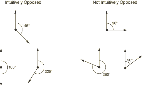
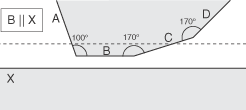
Figure 15–5 illustrates a simple example of the contact pair requirements.
Figure 15–5 Two bodies involved in potential contact. The bodies are rendered in two dimensions for simplicity.
After using the separation and orientation checks to compile a list of potential contact pairs, the contact detection tool can perform a series of additional checks that adjust the surface definitions to make them more useful and realistic. All three of these additional checks are optional, but they are enabled by default.
Extending surfaces
By default, any surface identified by the contact detection tool is extended to include adjacent model faces within 20°, even if the adjacent faces do not meet the separation and orientation requirements. The 20° angle is measured as the offset between the normals of the detected surface and the adjacent face at the common edge. You can modify the extension angle using the Extend each surface found by angle option. As faces are added to the surface definition, Abaqus/CAE also checks any faces adjacent to the newly added faces. Abaqus/CAE eliminates any redundant definitions if an extended surface incorporates a face from a separately defined contact pair. For example, consider extending surfaces within 20° for the model in Figure 15–5. Abaqus/CAE creates a single contact pair: one surface consists of face X, and the other surface consists of faces B, C, and D. Face D is within 20° of face C, which is within 20° of face B; the redundant contact pair consisting of face C and face X is eliminated, since it is incorporated by the larger contact pair.
Merging contact pairs within a specified angle
You can use the Merge pairs when surfaces are within angle option to combine multiple contact pairs into a single definition. The faces involved in the contact pairs must be adjacent and they must lie within the specified angle (as described above). The merge option does not extend faces; it only combines positively identified contact pairs. By default, contact pairs with surfaces within 20° are merged by the contact detection tool. The merge option is typically used as an alternative to surface extension to merge contact pair candidates automatically without extending surface definitions beyond the separation tolerance. For example, merging pairs within 20° without extending surfaces for the model in Figure 15–5 results in a single contact pair: one surface consists of face X, and the other surface consists of faces B and C.
Checking for surface overlap
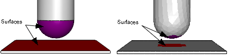
By default, the contact detection tool eliminates any contact pairs whose surfaces do not “overlap”; two surfaces do not overlap if a normal from any point on one of the surfaces does not pass through the opposing surface. For example, the surfaces in Figure 15–6 do not overlap, even though they may pass the separation and orientation checks.
You can suppress the check for surface overlap and allow the creation of contact pairs for non-overlapping surfaces by using the Include opposing surfaces that do not overlap option.Abaqus/CAE begins searching a model comprised of geometry by dividing the model into individual faces. A face consists of the area enclosed in connected geometric edges or partitions. Once all of the faces are identified, Abaqus/CAE compares the faces to determine if they meet the separation and orientation requirements, then defines surfaces from the faces by applying extension, merging, and overlap checks (see “Additional criteria for defining contact pairs” above). Any two surfaces that meet all of the requirements are flagged as a contact pair candidate.
Abaqus/CAE automatically assigns the master and slave designations to surfaces in a detected contact pair. Analytical rigid or discrete rigid surfaces are always assigned the master role; if the contact pair involves two rigid surfaces, the assignment of master and slave roles is arbitrary. For contact pairs involving two deformable surfaces, Abaqus/CAE first determines if the surface geometry has been meshed and assigns the master role to the surface with the coarser mesh. If mesh information is unavailable, the surface with the larger area becomes the master surface. The algorithm that assigns master and slave roles does not account for dissimilar underlying stiffness or element assignments; if these factors play a significant role in your contact interactions, you should review the master and slave assignments before creating an interaction. For further discussion of master and slave assignments, see “Selecting surfaces used in contact pairs” in “Defining contact pairs in Abaqus/Standard,” Section 36.3.1 of the Abaqus Analysis User's Guide.
Contact detection also works with mesh models. The search algorithm for meshed models works in much the same way as with geometry, but it uses element faces instead of geometric faces. By default, Abaqus/CAE only searches for contact pairs between separate part instances. Mesh models that are imported into Abaqus/CAE often consist of only a single part instance; therefore, you should enable searching within the same instance before using contact detection on these models (see “Defining contact within the same instance and self-contact” below for more details).
Warning: Unlike geometry-based searches, the reported separation between surfaces for mesh-based surfaces is not necessarily the distance between the exact points of closest approach, but rather a close approximation. If the specified search tolerance is very large compared to the characteristic element size, the accuracy of this approximation is greatly reduced.
Before defining surfaces on element faces, Abaqus/CAE applies the same extension, merging, and overlap checks as with geometry faces (see “Additional criteria for defining contact pairs” above). Because element faces are typically much smaller than geometric faces, you should always allow some extension of the surfaces to get ample coverage from a surface definition; Figure 15–7 compares the created surfaces for geometry and meshed geometry when no surface extension is allowed.
Figure 15–7 Discrepancies between created surfaces when no surface extension is allowed for geometry (left) and meshed geometry (right).
If you remesh your model, any surfaces defined on elements faces may become invalid. By extension, the interactions and constraints based on these faces also become invalid.
When assigning master and slave designations to the mesh surfaces, rigid surfaces always become the master; if the contact pair involves two rigid surfaces, the assignment of master and slave roles is arbitrary. For contact pairs involving two deformable surfaces, Abaqus/CAE considers the mesh densities on each surface; the surface with the coarser mesh becomes the master surface. If the mesh densities on the two surfaces are equivalent, the assignment of master and slave roles is arbitrary. The algorithm that assigns master and slave roles does not account for dissimilar underlying stiffness or element types; if these factors play a significant role in your contact interactions, you should review the master and slave assignments before creating an interaction. For further discussion of master and slave assignments, see “Selecting surfaces used in contact pairs” in “Defining contact pairs in Abaqus/Standard,” Section 36.3.1 of the Abaqus Analysis User's Guide.
The contact detection tool does not detect contact between geometry and orphan elements or analytical surfaces and orphan elements. If your model includes part instances that have been meshed from geometry, you can use the options on the Advanced tabbed page of the contact detection dialog box to indicate whether these instances should be treated as geometry (the default) or an element mesh during the search. If your model contains instances of both geometry and orphan mesh elements, you should first mesh all of the geometries, then perform a mesh-based search to capture all possible contact pairs.
In most cases the geometry is a more faithful representation of the object being modeled than the meshed geometry. In addition, geometry-based interactions and constraints are not affected by remeshing. However, the mesh is the geometry used in the analysis. Mesh discretization can lead to slight disparities in separation distances between the two representations, which may become important in precise analyses. After performing a search, you can check individual contact pairs for disparities between the native and meshed geometry by using the Recalculate Separation option.
If two faces in an assembly intersect at any point, the contact detection tool reports those faces as an overclosed contact pair. Overclosed contact pairs that appear in the contact pair candidates table must still meet the surface orientation requirements. A red zero in the Separation column indicates that the two surfaces in the contact pair are intersecting.
Note: A black zero in the Separation column implies that the two surfaces are exactly touching at their closest points. There is no overclosure or intersection in this situation.
You should visually inspect all overclosed surfaces before creating contact interactions. Models with severe overclosures should be adjusted to remove the overclosures (or at least lessen their severity). Minor overclosures can be addressed by using the contact adjustment options (available in the contact pair candidates table) or the interference fit options (available in the contact interaction editor).
Faces must intersect to be reported as overclosed. If a face is enclosed entirely within another part instance, the automatic contact detection tool does not report that face as being overclosed. Such a face may still meet the separation and orientation requirements with respect to an external face on the enclosing instance. By default, Abaqus/CAE eliminates enclosed faces from the contact pair candidates table because the surfaces do not “overlap” (see “Additional criteria for defining contact pairs”). If you disable the overlap checks, Abaqus/CAE reports a contact pair candidate for enclosed faces, but the contact pair candidates table does not provide any indication that the surfaces are overclosed or penetrating. Because the contact detection tool does not recognize these faces as overclosed, the adjustment options that are applied to overclosed surfaces by default (see “Default interaction and constraint parameters,” Section 15.6.3) are not applied to this contact pair. If an enclosed face is embedded deeper than the separation tolerance from any external face, the automatic contact detection tool does not identify those faces as a contact pair candidate.
As an example, consider the model in Figure 15–8.
Figure 15–8 In this model, one end of the cylindrical part instance is entirely enclosed within another part instance.
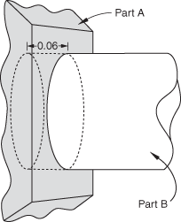
Although the contact detection tool does not recognize completely enclosed surfaces as being overclosed, such surfaces are still treated as overclosures during an analysis. Severe overclosures commonly lead to convergence difficulties. When reviewing overclosed contact pairs in the contact pair candidates table, check adjoining surfaces for fully enclosed faces.
You can use the contact detection tool to define contact between different areas of the same part instance or model instance. This capability is particularly useful for complicated models that are imported into Abaqus/CAE as a single part instance. If you enable the Include pairs with surfaces on the same instance option, Abaqus/CAE checks different geometry or element faces on the same part instance or model instance to determine whether or not they meet the separation and orientation requirements. Surfaces and contact pairs are defined on any faces that meet the requirements.
In some situations, surface extension options cause the master and slave surfaces to overlap. If the master surface and the slave surface consist of the same faces, Abaqus/CAE automatically adjusts the contact pair to create a self-contact interaction, in which a surface contacts itself during deformation. A single surface is created in this situation.
If a section definition has been assigned to a shell part, the contact detection tool accounts for the thickness of the shell in separation calculations. The reported separation has been adjusted according to the thickness and offset specified in the shell section assignment. You can use the Account for shell thickness and offset option to ignore shell section properties during a contact detection search. Varying thickness distributions are never considered in the separation calculations.
The contact detection tool automatically selects a shell side on which to create a surface (see “Specifying a particular side or end of a region,” Section 73.2.5, for more information). The side is selected such that the surface normals at the points of closest approach are intuitively opposed.
When working with a model that includes orphan shell elements, make sure that the element normal orientations are consistent between elements; that is, the positive element faces (SPOS) should all be located on the same side of the shell structure (see “Shell elements: overview,” Section 29.6.1 of the Abaqus Analysis User's Guide, for more information). If the element normal orientations are inconsistent, Abaqus/CAE misinterprets the angles between the element faces, and the surface extension and merge operations do not function appropriately.
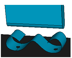
For certain spline-based shells or faces, the same surface may interact with both sides of a shell (see Figure 15–9, for example).
Normally you would define a separate contact pair involving each side of the shell. The contact detection tool, however, cannot create multiple contact pairs that involve the same two faces; it will define a single contact pair and select the shell side according to the orientation at the point of closest approach. You must manually define another contact pair for the other side of the shell.The contact detection tool does not create any double-sided surfaces. If appropriate, you can edit the definition of a created surface in the Model Tree to make it double-sided (see “Editing sets and surfaces,” Section 73.3.5).