
Select Shape![]() Shell
Shell![]() Sweep from the main menu bar to add a swept shell feature to the part in the current viewport. You can add a swept shell feature only to three-dimensional parts.
Sweep from the main menu bar to add a swept shell feature to the part in the current viewport. You can add a swept shell feature only to three-dimensional parts.
You add a swept shell feature by first defining a sweep path, then defining a sweep profile. There are different methods available for defining each component:
You can define a sweep path either by sketching the path on a selected face or by selecting a series of edges or wires that you want the sweep path to follow. The sketch method provides greater flexibility but supports only two-dimensional paths. The edge/wire method enables you to define a three-dimensional sweep path along a feature such as a spline wire or a set of edges in a three-dimensional part.
You can define a sweep profile either by sketching a sweep profile using the Sketcher or by selecting one of the faces in your model as the profile. The sweep profile is initially perpendicular to the path; you can keep this orientation constant along the entire sweep path, or you can keep the sweep profile perpendicular to the sweep path as it is swept along its length.
The sweep path (a spline) and the sweep profile are shown in the following figure:
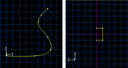

The sketch or set of edges defining the sweep path and the sketch, edge, or edges defining the sweep profile combine to define the swept shell feature; both the sweep path and the sweep profile can be modified using the Feature Manipulation toolset if you define them using the Sketcher. You can define a swept shell whose sweep profile is offset from the sweep path. In this case Abaqus/CAE moves the sweep path to a parallel location that passes through the sweep profile and creates the swept shell feature at that location.
As you define your sweep feature, you can apply a twist or draft to it. For more information about these tools, see “What types of features can you create?,” Section 11.9. You can toggle on Keep profile normal constant to maintain the same orientation for the sweep profile as it travels along the sweep path; if this option is toggled off, the sweep profile orientation changes with the normal to the sweep path. In addition, you can toggle on Keep internal boundaries in the Feature Manipulation toolset to maintain any faces or edges that are generated between the swept shell feature and the existing part. The internal boundaries can create regions that can be structured or swept meshed without having to resort to partitioning.
To add a swept shell feature:
From the main menu bar, select Shape![]() Shell
Shell![]() Sweep.
Sweep.
Abaqus/CAE displays prompts in the prompt area to guide you through the procedure.
Tip:
You can also add a swept shell feature using the ![]() tool, located with the shell tools in the Part module toolbox. For a diagram of the tools in the Part module toolbox, see “Using the Part module toolbox,” Section 11.17.
tool, located with the shell tools in the Part module toolbox. For a diagram of the tools in the Part module toolbox, see “Using the Part module toolbox,” Section 11.17.
If you want to sketch the sweep path, do the following:
From the Path options, select Sketch and click ![]() .
.
Abaqus/CAE displays prompts in the prompt area to guide you through the procedure.
If desired, specify the method you want to use to select an origin for your sketch of the swept solid feature. Select one of the following options from the Sketch Origin field in the prompt area:
Select Auto-Calculate to place the sketch origin automatically.
Select Specify to define a custom sketch origin.
Select Session Default to use the custom origin you specified earlier in the session.
Select the planar face on which to sketch the sweep path. If no suitable face exists, you can select a datum plane.
Tip: If you are unable to select the desired planar face, you can use the Selection toolbar to change the selection behavior. For more information, see “Using the selection options,” Section 6.3.
If you selected Specify as the Sketch Origin method, specify the origin location by clicking a point in the viewport or by entering the three-dimensional coordinates of the origin in the prompt area. You can also set this custom origin as the default origin for all sketches in your session by toggling on Set as session default.
Select an edge and the orientation of the edge on the Sketcher grid. The edge must not be perpendicular to the selected face. By default, the selected edge will appear vertical and on the right side of the Sketcher grid. To choose a different orientation for the edge, click the arrow on the right side of the dialog box and choose an orientation from the list that appears.
Tip: If there is no straight edge with the desired orientation, you can create a datum axis. You can then select the datum axis to control the orientation of the part on the Sketcher grid.
Abaqus/CAE highlights the selected edge, enters the Sketcher, and rotates the part so that the selected face aligns with the plane of the Sketcher grid and the selected edge aligns with the grid in the desired orientation.
If you are unsure of the part's orientation relative to the Sketcher grid, use the view manipulation tools from the View Manipulation toolbar to view its position. Use the reset view tool ![]() to return to the original view.
to return to the original view.
Sketch the sweep path. The sweep path must meet the following guidelines:
The path can be closed, but the ends must meet smoothly; for example, the ends should not meet at a corner. For examples of valid sweep paths, see “Defining the sweep path and the sweep profile,” Section 11.13.8.
The path must be continuous; for example, it must not branch.
The resulting solid cannot intersect with itself.
Abaqus/CAE exits the Sketcher and restores the original view of the part. A highlighted line indicates the sweep path and its direction. Abaqus/CAE also reopens the Create Shell Sweep dialog box and adds the word (Defined) next to the Sketch label in the Path options to indicate that the sweep path has been defined in the Sketcher.
If you want to specify the sweep path as a series of edges or wires, do the following:
From the Path options, select Edges and click ![]() .
.
Abaqus/CAE displays prompts in the prompt area to guide you through the procedure.
If desired, specify in the prompt area whether you want to select the edges in your sweep path individually or by edge angle. For more information about selecting objects, see “Using the angle and feature edge method to select multiple objects,” Section 6.2.3.
Select the edges you want to include in the sweep path.
Abaqus/CAE shows the sweep path on your part and indicates the sweep direction.
In the prompt area, click Yes to confirm the sweep path direction or click Flip to reverse the sweep path direction.
Abaqus/CAE reopens the Create Shell Sweep dialog box and adds the word (Defined) next to the Edges label in the Path options to indicate that the sweep path has been defined using a series of edges.
If you want to sketch the sweep profile, do the following:
From the Profile options, select Sketch and click ![]() .
.
Abaqus/CAE displays prompts in the prompt area to guide you through the procedure.
Sketch the sweep profile. The sweep profile must meet the following guidelines:
The profile must be closed.
The resulting solid cannot intersect with itself.
Abaqus/CAE exits the Sketcher and restores the original view of the part.
Select an edge and the orientation of the edge on the Sketcher grid. The selected edge must not be parallel to the sweep path direction. By default, the selected edge will appear vertical and on the right side of the Sketcher grid. To choose a different orientation for the edge, click the arrow on the right side of the dialog box and choose an orientation from the list that appears.
Abaqus/CAE highlights the selected edge, enters the Sketcher again, and rotates the part so that the Sketcher grid lies on a plane normal to the beginning of the sweep path with the sweep path direction pointing out of the screen. In addition, the selected edge aligns with the grid in the desired orientation. The intersection of two dashed lines indicates the origin of the sweep path. Abaqus/CAE also reopens the Create Shell Sweep dialog box and adds the word (Defined) next to the Sketch label in the Profile options to indicate that the sweep profile has been defined in the Sketcher.
If you want to select one or more edges as the sweep profile, do the following:
From the Profile options, select Edges and click ![]() .
.
Abaqus/CAE displays prompts in the prompt area to guide you through the procedure.
Select one or more edges from the viewport.
Abaqus/CAE highlights the selected face and displays the Create Shell Sweep dialog box.
Abaqus/CAE reopens the Create Shell Sweep dialog box and adds the word (Defined) next to the Edges label in the Profile options to indicate that the sweep profile has been defined using one or more edges.
If desired, do one of the following:
Toggle on Include twist, and enter the pitch. The pitch is the extrusion distance in which a 360° twist would occur. The sketched extrusion profile must include an isolated point that indicates the center of twist.
Toggle on Include draft, and enter the draft angle (greater than 90° and less than 90°). A positive draft angle indicates that external faces of the profile expand and internal faces contract. You cannot apply a draft if the Keep profile normal constant option is selected.
Toggle on Keep profile normal constant to maintain the same profile orientation along the entire sweep path. If this option is toggled off, Abaqus/CAE adjusts the profile orientation so that the angle between the sweep profile and the normal to the sweep path is always constant. You cannot toggle on this option if the Include draft option is selected.
Toggle on Keep internal boundaries to maintain any faces or edges that are generated between the swept solid feature and the existing part. The internal boundaries can create regions that can be structured or swept meshed without having to resort to partitioning.
Click OK to create the new swept shell.
