Product: Abaqus/Explicit

User subroutine VUINTERACTION:
can be used to define the mechanical and thermal interaction between contact surfaces;
must provide the entire definition of the interaction between the contact surfaces;
can utilize a user-specified tracking thickness to determine potential points of interaction on a surface (and thus which nodes should be passed into the subroutine);
can use and update solution-dependent state variables for node-to-face contact and node-to-analytical rigid surface contact; and
must be used with the general contact algorithm.
The use of user subroutine VUINTERACTION requires familiarity with the following terminology.
For efficiency, user subroutine VUINTERACTION considers only regions of two surfaces that are likely to be in contact or come into contact in a given increment. This likelihood is defined by a tracking thickness: only portions of surfaces separated by less than the tracking thickness in a given increment are passed into the subroutine; portions of the surfaces with a separation larger than the tracking thickness are ignored for the current increment. Surface thicknesses are accounted for in the separation calculations.
Abaqus/Explicit provides an internal default value for the tracking thickness, but a nondefault value can be specified; see “Tracking thickness when VUINTER or VUINTERACTION is used” in “User-defined interfacial constitutive behavior,” Section 37.1.6 of the Abaqus Analysis User's Guide. The tracking thickness is passed into VUINTERACTION using the variable rData(4).
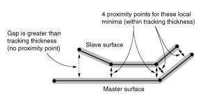
A proximity point is a potential point of interaction for you to consider in user subroutine VUINTERACTION. Each proximity point is primarily associated with a slave node or a point along a slave edge; the proximity point also references a corresponding, locally nearest point on the master surface within the tracking thickness. A proximity point exists for each pairing of slave node and proximal master surface point. Therefore, more than one proximity point may reference the same node on the slave surface but different points on the master surface if multiple local minimum distances to the slave node exist on the master surface; this phenomenon commonly occurs near the corners of a master surface. No proximity points exist for a slave node that is separated from the master surface by more than the tracking thickness. A two-dimensional representation for contact between portions of shell surfaces is shown in Figure 1.2.21–1.
Figure 1.2.21–1 Four proximity points are associated with three slave nodes in this surface pairing.
The number of proximity points currently being passed into user subroutine VUINTERACTION is nBlock. The array jSlvUid(nNodSlv,nBlock) gives the slave surface node numbers associated with the proximity points. The variable nNodSlv indicates whether a single slave node (for node-to-face contact) or two slave nodes of an edge (for edge-to-edge contact) are associated with each proximity point. Similarly, the array jMstUid(nNodMst,nBlockAnal) gives the master surface node numbers associated with the proximity points; the nodes can belong to a facet, an edge, or an analytical surface. The variable nNodMst indicates the number of master nodes associated with each proximity point.
An Abaqus/Explicit model can be defined in terms of an assembly of part instances (see “Defining an assembly,” Section 2.10.1 of the Abaqus Analysis User's Guide). In such models a node number is an internally generated node number. If the original node number and part instance name are required, call the utility routine VGETPARTINFO (see “Obtaining part information,” Section 2.1.5).
The array dircos defines the direction cosines of a local coordinate system for each proximity point. The first local direction corresponds to the contact normal direction from the perspective of the slave node. The second and third local directions correspond to two orthogonal tangent directions ![]() and
and ![]() , which are set as follows:
, which are set as follows:
If the master surface is a cylindrical analytical surface, the second local direction corresponds to the generator direction (see “Analytical rigid surface definition,” Section 2.3.4 of the Abaqus Analysis User's Guide), and the third local direction is the cross product of the first and second local directions.
If the master surface is an analytical surface of revolution, the third local direction corresponds to the hoop direction, and the second local direction is the cross product of the third and first local directions.
If the master surface is element-based, the tangential directions are based on the slave normal and the line connecting the first and third nodes on the master facet.
A positive normal stress denotes a pressure directed into the surface (opposite the local normal direction). Positive shear stresses denote shear tractions in the direction of the local surface tangents.
A positive flux indicates heat flowing into a surface, and a negative flux denotes heat leaving the surface. Flux must be specified for both surfaces, and they need not be equal and opposite so that effects such as frictional dissipation and differential surface heating can be modeled.
      subroutine vuinteraction (
C Read/Write -
     *   stress, fluxSlv, fluxMst,
     *   state, sed,
C Write only -
     *   sfd, scd, spd, svd,
C Read only -
     *   nBlock, nBlockAnal, nBlockEdge,
     *   nNodState, nNodSlv, nNodMst, nDir,
     *   nStates, nProps, nTemp, nFields,
     *   jFlags, rData,
     *   surfInt, surfSlv, surfMst,
     *   jSlvUid, jMstUid, props,
     *   penetration, drDisp, dRot, dircos, stiffDef, conductDef,
     *   coordSlv, coordMst, areaProx, shapeSlv, shapeMst,
     *   tempSlv, tempMst, dTempSlv, dTempMst,
     *   fieldSlv, fieldMst, dFieldSlv, dFieldMst )
C
      include `vaba_param.inc'
C
      dimension stress(nDir,nBlock),
     *   fluxSlv(nBlock),
     *   fluxMst(nBlock),
     *   state(nStates,nNodState,nBlock),
     *   sed(nBlock),
     *   sfd(nBlock),
     *   scd(nBlock),
     *   spd(nBlock),
     *   svd(nBlock),
     *   jSlvUid(nNodSlv,nBlock),
     *   jMstUid(nNodMst,nBlockAnal),
     *   props(nProps),
     *   penetration(nBlock),
     *   drDisp(nDir,nBlock),
     *   dRot(2,2,nBlock),
     *   stiffDef(nBlock),
     *   conductDef(nBlock),
     *   dircos(nDir,nDir,nBlock),
     *   coordSlv(nDir,nNodSlv,nBlock),
     *   coordMst(nDir,nNodMst,nBlockAnal),
     *   areaProx(nBlock),
     *   shapeSlv(nNodSlv,nBlockEdge),
     *   shapeMst(nNodMst,nBlockAnal),
     *   tempSlv(nBlock),
     *   tempMst(nBlockAnal),
     *   dTempSlv(nBlock),
     *   dTempMst(nBlockAnal),
     *   fieldSlv(nFields,nBlock),
     *   fieldMst(nFields,nBlockAnal)
     *   dFieldSlv(nFields,nBlock),
     *   dFieldMst(nFields,nBlockAnal)
C
      parameter( iKStep    = 1,
     *           iKInc     = 2,
     *           iLConType = 3,
     *           nFlags    = 3 )
C
      parameter( iTimStep   = 1,
     *           iTimGlb    = 2,
     *           iDTimCur   = 3,
     *           iTrackThic = 4,
     *           nData      = 4 )
C
      dimension jFlags(nFlags), rData(nData)
C
      character*80 surfInt, surfSlv, surfMst
C
      user coding to define stress,
      and, optionally, fluxSlv, fluxMst, state, sed, sfd, scd, spd,
      and svd
C
      return
endstress(nDir, nBlock)
On entry this array contains the stress defined in the local system at the proximity points during the previous time increment. It must be updated to the stress at the interface in the current time increment.
fluxSlv(nBlock)
On entry this array contains the flux entering the slave surface during the previous time increment. It must be updated to the flux entering the slave surface during the current increment.
fluxMst(nBlock)
On entry this array contains the flux entering the master surface during the previous time increment. It must be updated to the flux entering the master surface during the current time increment.
state(nStates,nNodState,nBlock)
This array contains the user-defined solution-dependent state variables for the proximity points. The use of the state variables is applicable only for node-to-face contact. See “User-defined interfacial constitutive behavior,” Section 37.1.6 of the Abaqus Analysis User's Guide, for more information on the size of this array. This array will be passed in containing the values of these variables prior to the call to user subroutine VUINTERACTION.
If any of the solution-dependent state variables is being used in conjunction with the interaction, it must be updated in this subroutine. These state variables need to be updated with care: outside the user subroutine these state variables are single-valued per slave node, but multiple proximity points may refer to the same slave node. Each proximity point may be passed into the user subroutine independently in a given increment, possibly on separate calls to the user subroutine; therefore, you may end up advancing the state variables for the associated node multiple times for a single time increment. To keep track of whether or not a node state is advanced, you may want to use one of the state variables exclusively for this purpose. You could set that selected state variable to the current increment number and update the state only if it is not already set to the current increment number.
sed(nBlock)
On entry this array contains the elastic energy density at the proximity points at the beginning of the increment. It can be updated to contain the elastic energy density at the end of the current time increment. These values contribute to the output variable ALLSE and have no effect on other solution variables. The use of this variable is applicable only for node-to-face contact.
sfd(nBlock)
This array can be updated to contain the increment in frictional dissipation at each proximity point (units of energy per unit area). These values contribute to the output variables SFDR and ALLFD and have no effect on other solution variables. The use of this variable is applicable only for node-to-face contact.
scd(nBlock)
This array can be updated to contain the increment in creep dissipation at each proximity point (units of energy per unit area). These values contribute to the output variables SFDR and ALLCD and have no effect on other solution variables. The use of this variable is applicable only for node-to-face contact.
spd(nBlock)
This array can be updated to contain the increment in plastic dissipation at each proximity point (units of energy per unit area). These values contribute to the output variables SFDR and ALLPD and have no effect on other solution variables. The use of this variable is applicable only for node-to-face contact.
svd(nBlock)
This array can be updated to contain the increment in viscous dissipation at each proximity point (units of energy per unit area). These values contribute to the output variables SFDR and ALLVD and have no effect on other solution variables. The use of this variable is applicable only for node-to-face contact.
nBlock
Number of proximity points to be processed in this call to VUINTERACTION.
nBlockAnal
1 for analytical rigid master surface; nBlock otherwise.
nBlockEdge
nBlock for edge type slave surface; 1 otherwise.
nNodState
1 for node-to-face and node-to-analytical rigid surface contact; not applicable for edge-to-edge contact.
nNodSlv
1 for node-to-face and node-to-analytical rigid surface contact; 2 for edge-to-edge contact.
nNodMst
1 for analytical rigid master surface; 2 for edge-type master surface; 4 for facet-type master surface.
nDir
Number of coordinate directions at the proximity points (equal to 3).
nStates
Number of user-defined state variables.
nProps
User-specified number of property values associated with this interaction model.
nTemp
1 if the temperature is defined and 0 if the temperature is not defined.
nFields
Number of predefined field variables.
jFlag(1)
Step number.
jFlag(2)
Increment number.
jFlag(3)
1 for node-to-face contact, 2 for edge-to-edge contact, and 3 for node-to-analytical rigid surface contact.
rData(1)
Value of step time.
rData(2)
Value of total time.
rData(3)
Current increment in time from ![]() to
to ![]() .
.
rData(4)
This variable contains the value of the tracking thickness specified for the surface interaction.
surfInt
User-specified surface interaction name, left justified.
surfSlv
Slave surface name, currently set to a blank.
surfMst
Master surface name, currently set to a blank.
jSlvUid(nNodSlv,nBlock)
This array lists the surface node numbers of the slave surface nodes associated with each proximity point.
jMstUid(nNodMst,nBlockAnal)
This array lists the surface node numbers of the master surface nodes that make up the facet, edge, or analytical rigid surface associated with each proximity point.
props(nProps)
User-specified vector of property values to define the interaction between the tracking surfaces.
penetration(nBlock)
The relative position of the proximity points, with respect to the master surface, in the normal direction (a positive value indicates a penetration, and a negative value indicates a gap) during the current time increment.
drDisp(nDir,nBlock)
An array containing the increments in relative positions of the proximity points with respect to the associated master surfaces during the current time increment.
dRot(2,2,nBlock)
This argument is currently undefined.
stiffDef(nBlock)
Values of the default penalty stiffnesses (stress per unit penetration, units of ![]() ).
).
conductDef(nBlock)
Values of the default penalty conductances (units of ![]() ).
).
dircos(nDir,nDir,nBlock)
Direction cosines of the local surface coordinate system. The first array index corresponds to the components of the local directions, and the second array index corresponds to the local direction number. The first direction (dircos(1..nDir,1,...)) is the normal to the surface. The second direction (dircos(1..nDir,2,...)) is the first surface tangent. For a three-dimensional surface, the third direction (dircos(1..3,3,...)) is the second surface tangent. If the master surface is an analytical rigid surface, the numbers in dircos are valid only if the corresponding parts in penetration are valid (i.e., not equal to r_MaxVal).
coordSlv(nDir,nNodSlv,nBlock)
Array containing the nDir components of the current coordinates of the proximity points.
coordMst(nDir,nNodMst,nBlockAnal)
Array containing the nDir components of the current coordinates of the nodes on the master surface. If the master surface is an analytical rigid surface, this array is passed in as a dummy array.
areaProx(nBlock)
Contact area associated with a proximity point. The sum of the contact areas among all proximity points associated with a single slave node equals the surface area associated with that slave node (equal to 1 for node-based surface nodes). Therefore, the contact area at a proximity point depends on the number of other proximity points currently associated with the same slave node. A proximity point contributes a contact normal force to the associated slave node that is equal to stress(1,k) multiplied by areaProx(k).
shapeSlv(nNodSlv,nBlockEdge)
For edge-to-edge contact this array contains the shape functions of the nodes of its slave edge, evaluated at the location of the contact point. If the contact is not edge-to-edge, this array is passed in as a dummy array.
shapeMst(nNodMst,nBlockAnal)
For node-to-face and edge-to-edge contact this array contains the shape functions of the nodes of its master surface, evaluated at the location of the contact point. If the master surface is an analytical rigid surface, this array is passed in as a dummy array.
tempSlv(nBlock)
Current temperature at the proximity points on the slave surface.
tempMst(nBlockAnal)
Current temperature at the points on the master surface closest to the proximity points.
dTempSlv(nBlock)
Increment in the temperature during the previous time increment at the proximity points on the slave surface.
dTempMst(nBlockAnal)
Increment in the temperature during the previous time increment at the points on the master surface closest to the proximity points.
fieldSlv(nFields,nBlock)
Current user-specified predefined field variables at the proximity points on the slave surface (initial values at the beginning of the analysis and current values during the analysis).
fieldMst(nFields,nBlockAnal)
Current user-specified predefined field variables at the points on the master surface closest to the proximity points (initial values at the beginning of the analysis and current values during the analysis).
dFieldSlv(nFields,nBlock)
Increment in the user-specified predefined field variables during the previous time increment at the proximity points on the slave surface.
dFieldMst(nFields,nBlockAnal)
Increment in the user-specified predefined field variables during the previous time increment at the points on the master surface closest to the proximity points.