| Abaqus Keywords Reference Guide |
|
| How to find keyword examples |
| Abaqus Keywords Reference Guide |
|
| How to find keyword examples |

This option is used to modify surface properties for surfaces that are involved in general contact interactions. It must be used in conjunction with the *CONTACT option.
Products: Abaqus/Standard Abaqus/Explicit Abaqus/CAE
Type: Model data in Abaqus/Standard; Model or history data in Abaqus/Explicit
Level: Model in Abaqus/Standard; Model or Step in Abaqus/Explicit
Abaqus/CAE: Interaction module
Use this parameter to specify the property type being assigned. To modify more than one type of surface property, include the *SURFACE PROPERTY ASSIGNMENT option more than once with different values for this parameter.
Set PROPERTY=BEAM SMOOTHING to control smoothing of beam segments in beam-to-beam contact. This parameter value applies only to Abaqus/Standard analyses.
Set PROPERTY=FEATURE EDGE CRITERIA to control which primary feature edges and secondary feature edges should be activated in the general contact domain.
Set PROPERTY=GEOMETRIC CORRECTION to assign geometric corrections.
Set PROPERTY=OFFSET FRACTION to assign the surface offset as a fraction of the surface thickness.
Set PROPERTY=THICKNESS to assign the surface thickness.
Set PROPERTY=VERTEX CRITERIA to control which nodes of feature edges should be considered vertex nodes in the general contact domain.
First line:
Surface name.
A scalar value between 0.0 and 0.5 (0.2 is the default).
Repeat this data line as often as necessary. If the beam smoothing assignments overlap, the last assignment applies in the overlap region.
First line:
Surface name. If the surface name is omitted, a default surface that encompasses the entire general contact domain is assumed.
A scalar value between 0° and 180° representing the cutoff feature angle (in degrees), PERIMETER EDGES, or NO FEATURE EDGES. The default is 45°. This field activates edges to participate in edge-to-surface contact.
This field is intentionally left blank and is unused.
A scalar value between 0° and 180° representing the cutoff feature angle (in degrees), PERIMETER EDGES, or NO FEATURE EDGES. The entry on this field activates edges to participate in edge-to-edge contact. The default is NO FEATURE EDGES.
Repeat this data line as often as necessary. If the feature edge criteria assignments overlap, the last assignment applies in the overlap region.
First line:
Surface name. A non-blank surface name is required if the ALL EDGES or PICKED EDGES options are specified. If the surface name is omitted when using the PERIMETER EDGES, NO FEATURE EDGES, or cutoff feature angle options, a default surface that encompasses the entire general contact domain is assumed.
The criterion for primary feature edges. PERIMETER EDGES (default), ALL EDGES, PICKED EDGES, NO FEATURE EDGES, or a scalar value representing the cutoff feature angle (in degrees).
The criterion for secondary feature edges. ALL REMAINING EDGES, PERIMETER EDGES, PICKED EDGES, or a scalar value representing the cutoff feature angle (in degrees).
Repeat this data line as often as necessary. If the feature edge criteria assignments overlap, the last assignment applies in the overlap region.
First line:
Surface name.
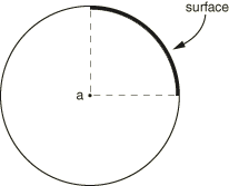
CIRCUMFERENTIAL.
Global X-coordinate of point a, the approximate center (origin) of the circular arc (see Figure 18.58–1).
Global Y-coordinate of point a, the approximate center (origin) of the circular arc.
Repeat this data line as often as necessary. If the geometry correction assignments overlap, the last assignment applies in the overlap region.
First line:
Surface name.
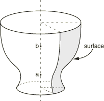
CIRCUMFERENTIAL.
Global X-coordinate of point a on the approximate axis of revolution for the surface (see Figure 18.58–2).
Global Y-coordinate of point a on the approximate axis of revolution for the surface.
Global Z-coordinate of point a on the approximate axis of revolution for the surface.
Global X-coordinate of point b on the approximate axis of revolution for the surface (see Figure 18.58–2).
Global Y-coordinate of point b on the approximate axis of revolution for the surface.
Global Z-coordinate of point b on the approximate axis of revolution for the surface.
Repeat this data line as often as necessary. If the geometry correction assignments overlap, the last assignment applies in the overlap region.
First line:
Surface name.
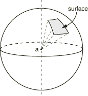
SPHERICAL.
Global X-coordinate of point a, the approximate center (origin) of the sphere (see Figure 18.58–3).
Global Y-coordinate of point a, the approximate center (origin) of the sphere.
Global Z-coordinate of point a, the approximate center (origin) of the sphere.
Repeat this data line as often as necessary. If the geometry correction assignments overlap, the last assignment applies in the overlap region.
First line:
Surface name.
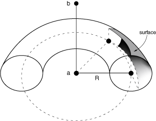
TOROIDAL.
Global X-coordinate of point a on the approximate axis of revolution for the surface (see Figure 18.58–4).
Global Y-coordinate of point a on the approximate axis of revolution for the surface.
Global Z-coordinate of point a on the approximate axis of revolution for the surface.
Global X-coordinate of point b on the approximate axis of revolution for the surface (see Figure 18.58–4).
Global Y-coordinate of point b on the approximate axis of revolution for the surface.
Global Z-coordinate of point b on the approximate axis of revolution for the surface.
Distance R of the center of the circular arc from the axis of revolution (see Figure 18.58–4).
Repeat this data line as often as necessary. If the geometry correction assignments overlap, the last assignment applies in the overlap region. The line joining point a and the center of the circular arc should be perpendicular to the axis of revolution.
First line:
Surface name.
Leave blank or specify NONE.
Repeat this data line as often as necessary. If the geometry correction assignments overlap, the last assignment applies in the overlap region.
First line:
Surface name. If the surface name is omitted, a default surface that encompasses the entire general contact domain is assumed. Faces specified on elements other than shell elements, membrane elements, rigid elements, and surface elements will be ignored.
ORIGINAL (default), SPOS, SNEG, or a value between –0.5 and 0.5. The offset defines the distance (as a fraction of the thickness) from the midsurface to the reference surface (containing the nodes of the element). Positive values of the offset are in the positive element normal direction. The default is ORIGINAL, which indicates that the offset specified in element section definitions (via the OFFSET parameter on *SHELL SECTION or *RIGID BODY) will be used.
Repeat this data line as often as necessary. If the offset fraction assignments overlap, the last assignment applies in the overlap region.
First line:
Surface name. If the surface name is omitted, a default surface that encompasses the entire general contact domain is assumed.
ORIGINAL (default), THINNING (available only in Abaqus/Explicit), or a scalar value representing a nominal thickness.
A constant scaling factor (default is 1.0).
Repeat this data line as often as necessary. If the thickness assignments overlap, the last assignment applies in the overlap region.
First line:
Surface name. If the surface name is omitted, a default surface that encompasses the entire general contact domain is assumed.
A scalar value between 10° and 90° representing the vertex angle threshold (in degrees) or NO VERTICES. The default is 20°. This field activates vertex nodes to participate in vertex-to-surface contact.
Repeat this data line as often as necessary. If the vertex criteria assignments overlap, the last assignment applies in the overlap region.