| Abaqus Keywords Reference Guide |
|
| How to find keyword examples |
| Abaqus Keywords Reference Guide |
|
| How to find keyword examples |

This option is used to define properties for a substructure. It is required for all substructures in a model.
Product: Abaqus/Standard
Type: Model data
Level: This option is not supported in a model defined in terms of an assembly of part instances.
Set this parameter equal to the name of the element set containing the substructures for which properties are being defined.
Set this parameter equal to the tolerance on the distance between usage level nodes and the corresponding substructure nodes. If this parameter is omitted, the default is a tolerance of 104 times the largest overall dimension within the substructure. If the parameter is given with a value of 0.0, the position of the retained nodes is not checked.
First (and only) line:
Value of the translation to be applied in the global X-direction.
Value of the translation to be applied in the global Y-direction.
Value of the translation to be applied in the global Z-direction.
First line:
Value of the translation to be applied in the global X-direction.
Value of the translation to be applied in the global Y-direction.
Value of the translation to be applied in the global Z-direction.
Enter values of zero to apply a pure rotation.
Second line:
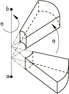
Global X-coordinate of point a on the axis of rotation (see Figure 18.51–1).
Global Y-coordinate of point a on the axis of rotation.
Global Z-coordinate of point a on the axis of rotation.
Global X-coordinate of point b on the axis of rotation.
Global Y-coordinate of point b on the axis of rotation.
Global Z-coordinate of point b on the axis of rotation.
Angle of rotation about the axis a–b, in degrees.
First line:
Value of the translation to be applied in the global X-direction.
Value of the translation to be applied in the global Y-direction.
Value of the translation to be applied in the global Z-direction.
Enter values of zero to apply a pure reflection.
Second line:
Enter a blank line.
Third line:
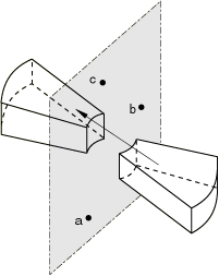
Global X-coordinate of point a in the plane of reflection (see Figure 18.51–2).
Global Y-coordinate of point a in the plane of reflection.
Global Z-coordinate of point a in the plane of reflection.
Global X-coordinate of point b in the plane of reflection.
Global Y-coordinate of point b in the plane of reflection.
Global Z-coordinate of point b in the plane of reflection.
Fourth line:
Global X-coordinate of point c in the plane of reflection.
Global Y-coordinate of point c in the plane of reflection.
Global Z-coordinate of point c in the plane of reflection.
First line:
Value of the translation to be applied in the global X-direction.
Value of the translation to be applied in the global Y-direction.
Value of the translation to be applied in the global Z-direction.
Second line:
Global X-coordinate of point a on the axis of rotation (see Figure 18.51–1).
Global Y-coordinate of point a on the axis of rotation.
Global Z-coordinate of point a on the axis of rotation.
Global X-coordinate of point b on the axis of rotation.
Global Y-coordinate of point b on the axis of rotation.
Global Z-coordinate of point b on the axis of rotation.
Angle of rotation about the axis a–b, in degrees.
Third line:
Global X-coordinate of point a in the plane of reflection (see Figure 18.51–2).
Global Y-coordinate of point a in the plane of reflection.
Global Z-coordinate of point a in the plane of reflection.
Global X-coordinate of point b in the plane of reflection.
Global Y-coordinate of point b in the plane of reflection.
Global Z-coordinate of point b in the plane of reflection.
Fourth line:
Global X-coordinate of point c in the plane of reflection.
Global Y-coordinate of point c in the plane of reflection.
Global Z-coordinate of point c in the plane of reflection.